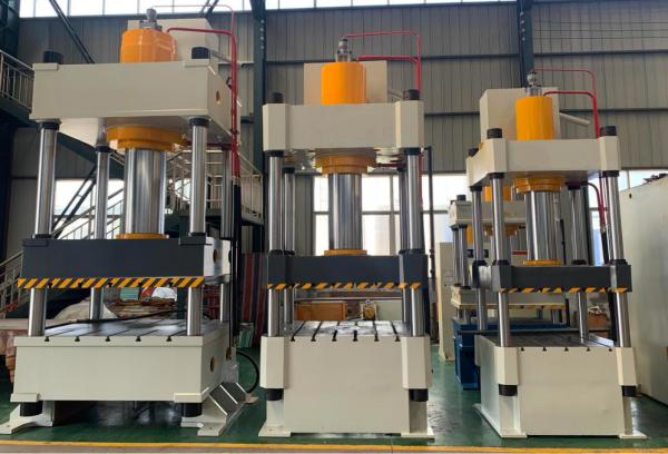
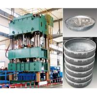
Kitchen Oven Press Machine/ Making Machine
Technical Proposal Description
1,The working environment of the machine
●Temperature: 0 ℃ -50 ℃.
●Humidity: Relative humidity below 35% -65%.
●Voltage: 380V 50Hz, 3 phase
●Installation site: less dust
● Altitude: below 1000M
2, Main technical parameters of the machine
| No | Name | UNit | YQ32-500T | YQ32-630T |
| 1 | Nominal force | KN | 5000 | 6300 |
| 2 | Maximum working pressure of liquid | MPa | 25 | 25 |
| 3 | Opening height | mm | 1500 | 1500 |
| 4 | Slide stroke | mm | 900 | 900 |
| 5 | Effective area of workbench: Left and right column inner * front
and rear edges | mm | 1500*1500 | 1500*1500 |
| 6 | Ejection Cylinder nominal force | KN | 1000 | 1000 |
| 7 | Ejection Cylinder stroke | mm | 300 | 300 |
3,Supply of main supporting parts:
| High pressure oil pump | Shaoyang Victor (http://www.shaoyecn.com) |
| Hydraulic system | Taifeng (http://www.taifenghydraulic.com) |
| Hydraulic cylinder | Factory |
| Motor | Huanqiu (www.js-hqdj.com) |
| an electric appliance | Schneider |
| Filling valve | Huadong hydraulic technology (http://www.hyzcn.com) |
| PLC | Haiwei http://www.jrdtec.net/ |
| Cylinder sealing ring | Guangzhou Research Institute (Imported Materials) |
4, Performance and characteristics:
This machine has an independent power mechanism and electrical
system, and adopts PLC centralized control. The process action is
manual and semi-automatic control mode. The hydraulic system adopts
integrated plug-in valves, with a compact structure, sensitive and
reliable action. Fast speed, low energy consumption, and low noise.
The working pressure and travel range of this series of products
can be adjusted according to work needs.
5, Structure Overview:
This machine consists of two main parts: the main engine and the
control mechanism, which are connected through oil pipelines and
electrical devices to form a whole. The main engine includes the
body, main cylinder device, etc. The control mechanism consists of
a hydraulic pump station, an electrical box, a mobile control
console, etc. The structure and function of each part are described
as follows:
1. Machine body: Adopting a three beam and four column structure,
it consists of upper crossbeam, slider, workbench, main cylinder,
ejection cylinder, column, control system, and electrical system
components.
2. Main cylinder: The main cylinder body is fixed to the table, and
the lower end of the piston rod is connected to the sliding block
with flanges and bolts. The piston head is divided into two oil
chambers in the cylinder with YX shaped sealing rings in opposite
directions. The outer circle of the guide sleeve is equipped with
O-ring sealing rings, which are locked with flanges and bolts to
ensure the sealing of the cylinder port. A dust ring is installed
on the cylinder flange to ensure dust prevention of the piston rod.
3. Limiting device: The limiting device is installed on the right
side of the machine and is mainly used to control the stroke
distance of the slider. It consists of shims, contactless travel
switches, etc.
4. Hydraulic station: The hydraulic pump consists of an oil tank,
an axial piston pump, an electric motor, a two-way plug-in valve, a
high-pressure self sealing oil filter, and an air filter. The fuel
tank is made of Q235 steel plate welded parts, and the front end is
equipped with a pressure gauge for observing pressure. Install a
level gauge in the fuel tank to observe the oil level.
5. Oil pump: axial piston pump. Its instructions can be found in
the user manual of the axial piston pump, and an overview is not
provided here.
6. Two way plug-in valve: Its structure mainly includes plug-in
parts, control cover plate, pilot control valve, and integrated
valve block parts.
a. Insert components: composed of valve inserts, seals, valve
bodies, etc. It can be a cone valve or a slide valve structure. Its
main function is to control the direction, pressure, flow rate,
etc. of oil flow in the oil circuit.
b. Control cover plate: composed of various micro pilot control
components and other hydraulic components embedded in the cover
plate. The main function is to fix the plug-in components. The
combination of various embedded micro pilot control components and
pilot control valves can control the working status of plug-in
valves. The control cover plate is divided into directional control
cover plate, pressure control cover plate, and flow control cover
plate.
c. Pilot control valve: an electromagnetic directional valve
installed on the control cover plate to control the action of the
plug-in, and its component is an electromagnetic directional valve.
d. Integrated valve block: used to install plugins, control cover
plates, and other control valves, to communicate the main oil
circuit and control oil circuit.
6, Overview of hydraulic system
The hydraulic system consists of energy conversion devices (oil
pumps and cylinders), as well as energy transfer devices (oil
tanks, oil pipelines), etc. With the help of electrical system
control, drive the slider to complete various action cycles.
7, Electrical control system
1. The machine is equipped with an independent electrical control
box, which can move both sides of the equipment freely, and
centralized buttons control the operation of the entire machine.
8, Operating System
1) It has two operation modes: inching and semi-automatic, and two
process operations: fixed stroke and constant pressure.
2) The slider stroke is adjusted by a contactless switch control
device.
3) The main cylinder pressure is adjusted by the pressure
regulating valve.
4) The pressure holding time can be freely set
|
|  |
9,More Details:


